Dimpled Duct
Air ducts are used everywhere, and their use is HVAC is constantly constrained by size limitations, there are certain situations that call for the use smaller ducts while maintaining airflow requirements. I had the idea to copy the dimples on a golf ball onto an air duct to increase its performance. I then tested this idea with a garage setup.

Test setup
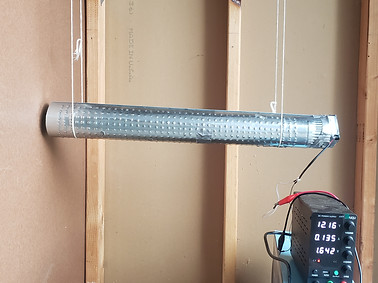
I used a 3" duct (2) with a small (aprox 3" x 3") 12V PC fan (3) taped to it to blow air through the duct. I hung it from the ceiling and had the exhaust just barely offset from a board (1), with the idea being that when the fan blew, it would push the duct away from the solid surface. Originally, I planned to measure the difference in force produced by looking at the angle of the string, but since the camera was in the middle of the duct and not at a point where the string meets the duct, the POV of the camera made this method difficult. Instead, I looked at the size of the gap made between the board (1) and the duct (2).
Control Trial
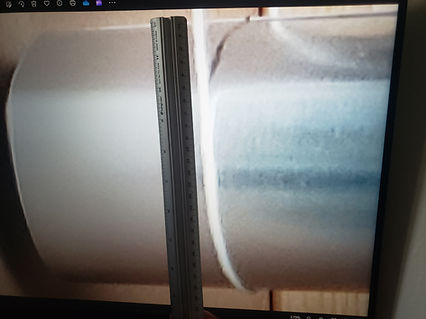
In the control trial, the fan was turned on and let run until the pipe stabilized, which was difficult since the garage door was open and any breeze would cause the setup to oscillate.
The distance between the board and the end of the duct was measured to be approximately 0.40±0.076". I found this by measuring the distance between the duct and the board on the computer (3.0cm±0.5cm), the diameter of the duct on my computer (22.5cm±0.5cm), and using a ratio between those two and the known duct diameter in real life (3") to determine the size of the gap.
The setup weighted 422.3 grams. and used 1.59 W of power.


Test Trial
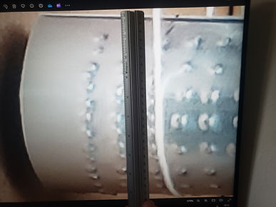
The same duct was used for the test trial, but dimples were punched into the duct in a 0.5" grid pattern with a hammer and punch. Duct tape was used to cover any holes where the punch went through the metal.
The duct was put on the same apparatus to be tested.
The distance between the board and the end of the duct was measured to be approximately 0.51±0.075". (Measured sizes of the zoomed in photo were 4.0cm±0.5cm and 23.5cm±0.5cm for the gap and the diameter, respectively.)
The setup weighted 426.2 grams. and used 1.64 W of power.

Results
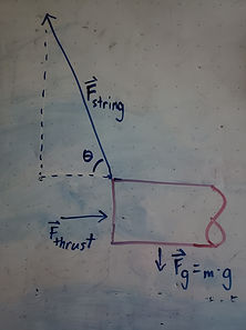
Using the method pictured to the right, I determined that the thrust provided in the control trial (smooth duct) is 33.1±6.3 mN and the thrust in the test trial (dimpled duct) is 42.3±6.2 mN. The efficiency for the ducts is 20.8±4.0 mN/W and 25.8±3.8 mN/W for the control and test trials, respectively.
These results suggest a 24% increase in efficiency when using a dimpled duct, but the error in these calculations is to large to say so with confidence.


Next Steps
The thing that would aid this experiment the most is reducing the error in the results either by getting better data or preforming more trials to average out the error.
Future studies could investigate varying the dimple density and/or the dimple pattern. Furthermore, more tests can be done with varied air velocities and air pressures either in CFD software or in experiments to determine the optimal operating conditions for dimpled ducts compared to traditional smooth ducts.
Update: This experiment will not be receiving updates in the foreseeable future because people prefer to have less efficient but quieter HVAC systems, so all of the codes are written to prioritize low noise levels. This design intentionally creates turbulence, which would have a major undesirable impact on noise levels.